File Formats & CAD Compatibility Help Center
Pattern Making & Development — File Formats & CAD Compatibility
1. Which CAD file formats are industry-standard for production patterns?
Primary production formats are Gerber .ZIP, clean DXF (AAMA conventions), and PLT/HPGL for plotting; these ensure factory compatibility and integrity.
- Our team of expert pattern engineers defaults to Gerber .ZIP and DXF for pattern geometry and PLT/HPGL for plotters.
- Include a flattened PDF proof for sewing-room verification.
For file-format consultation or format packaging, request the CAD File Conversion Service to confirm factory-ready outputs.
2. What is a Gerber .ZIP and when must it be used?
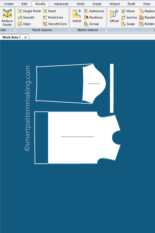
A Gerber .ZIP is the native AccuMark project bundle containing pieces, grades, markers, and layers for direct Gerber workflow on factory systems.
- Retains grading, notches, drill points, marker nests and layer structure—preferred when the factory uses Gerber AccuMark.
- Always export the full project bundle (.ZIP) rather than individual DXFs when targeting Gerber cutting rooms.
Request Gerber packaging via the CAD File Conversion Service for Gerber-optimized delivery.
3. What is DXF and why is it critical for manufacturers?
DXF is a universal vector exchange format that nearly all CAD and cutting systems accept, making it the standard for cross-platform pattern transfer.
- Provide a clean DXF with optimized point density and preserved notches/layers for reliable factory imports.
- Confirm whether the factory requires AAMA/DXF variants or raw DXF coordinates.
Convert and optimize DXF files using the CAD File Conversion Service.
4. What is the AAMA DXF standard and when should it be used?
AAMA DXF enforces apparel-specific layer and code conventions for consistent interpretation of notches, grainlines, and annotations across factories.
- Use AAMA when targeting factories that request standardized layer names and attribute codes for automation.
- Our team maps pattern annotations to AAMA layers to avoid misinterpretation in cutting rooms.
Order AAMA-compliant exports via the CAD File Conversion Service.
5. When are PLT / HPGL files required?
PLT/HPGL is required for driving legacy and many industrial plotters—use PLT for plotted markers and pattern proofs at 1:1 scale.
- PLT delivers pure line data with pen/plotter instructions; provide color-to-pen mappings when needed.
- Always include a PDF proof to verify scale and layer visibility before plotting.
Request PLT output and pen assignments through the CAD File Conversion Service.
6. How should file layers and naming conventions be structured?
Use a consistent layer schema: CUT, SEW, GRAIN, NOTCH, DRILL, ANNOTATION, and a clear file naming pattern for traceability.
- Recommended filename: style_design_base‑size_revision_date.zip (e.g., S123_Shirt_M‑01_2026‑04‑29.zip).
- Map layers to factory expectations and document mapping in a simple transfer spec file.
Provide required layer conventions on the order form or request a layer-mapping template via the project intake.
7. How to ensure scale accuracy before sending CAD files?
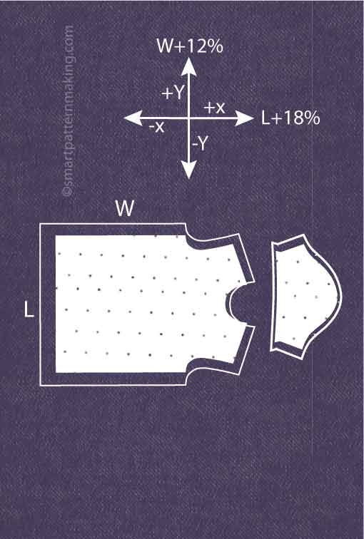
Embed a 10" or 25cm reference square and export a 1:1 flattened PDF for verification to guarantee exact scale in factory plotting.
- Include a PDF proof showing measurement callouts and at least three critical dimensions.
- Our team validates scale by checking the reference square and core POM values before delivery.
Add the PDF proof requirement to file exports or request validation via the CAD File Conversion Service.
8. What is point density and how does it affect DXF quality?
Point density defines curve resolution; optimal density balances smooth curves with manageable file size to prevent "dirty" DXF artifacts.
- Excess points create huge, slow files; too few points distort curves—use optimized bezier fitting.
- Our proprietary Smart Pattern System normalizes point density for smooth curves and efficient CAD operations.
Request point-density optimization when ordering DXF exports via the CAD File Conversion Service.
9. How to preserve notches, drill holes, and annotations across formats?
Keep all pattern marks on dedicated layers and use standardized symbols so notches/drill holes survive conversion between Gerber, DXF, and PLT.
- Notches as short vector ticks; drill holes as filled circles on a DRILL layer; label annotations in a non-print ANNOTATION layer.
- Verify after conversion with a flattened proof and measurement checks.
Include marking conventions in the project brief or request mapping assistance via the CAD File Conversion Service.
10. How to export for specific cutting systems (Gerber, Lectra, Tukatech)?
Export to the target system's preferred format (Gerber .ZIP, Lectra .mdl/.dxf variants, Tukatech DXF) and confirm layer/coding specs with the factory.
- Obtain factory CAD specifications before export; mismatched settings cause import errors.
- Our team produces tailored exports per cutter model to ensure plug-and-play compatibility.
Provide factory CAD specs and request a tailored export via the CAD File Conversion Service.
11. How to convert Gerber files to clean DXF without losing data?
Use AccuMark-native export with AAMA profiles and perform manual cleanup to preserve layers, notches, and curve fidelity in DXF outputs.
- Automated conversion followed by point optimization and layer reconciliation prevents data loss.
- Quality checks: compare key POM distances and overlay converted output on the original before delivery.
Request a Gerber→DXF conversion and QA pass through the CAD File Conversion Service.
12. What causes corrupt DXF files and how are they repaired?
Corruption stems from bad exports, incompatible CAD versions, or malformed polylines; repair requires re-export or reconstruction in AccuMark.
- Symptoms: missing curves, broken polylines, or unreadable file in target software.
- Repair workflow: validate in Gerber, re-export with correct DXF version, then run a cleanup script and manual reconstruction if needed.
Submit corrupt files for diagnosis and repair via the CAD File Conversion Service.
13. Can seam allowances be added or removed during export?
Yes—seam allowances can be toggled during export: deliver either "with seam allowance" patterns or "net" patterns without seam allowance per factory request.
- Document which layers include seam allowance and maintain a net-copy layer for downstream processes like marker making.
- Our team applies or removes seam allowance algorithmically, then verifies critical edge measurements.
Specify seam allowance requirements when ordering exports via the CAD File Conversion Service.
14. How should nested graded sets vs separated-size files be delivered?
Deliver separated-size files for production cutting and nested-overlays for visual review—both formats serve distinct production needs.
- Separated-size DXFs are required by most cutting rooms; nested visualizations help QA grading transitions.
- Include a graded spec sheet (POM) with separated files for factory intake.
Request separated-size exports and graded nests via the Grading & Export Service.
15. How to QC CAD files before sending to factory?
Run automated geometry checks, verify reference square scale, confirm POM key measures, and produce a flattened PDF proof for visual sign-off.
- Checks include seam length parity, notch alignment, drill hole positions, and layer completeness.
- Document results in a short QA checklist attached to the delivery package.
Include a CAD QC pass when ordering exports through the CAD File Conversion Service.
16. What export settings in Gerber ensure best DXF compatibility?
Use AAMA DXF profile, set DXF version to recommended factory version, enable true curves export, and export as separate-size DXFs when required.
- Disable unnecessary auxiliary layers; include a PDF proof and layer-map document with the export.
- Our team follows factory-provided export templates to eliminate import errors.
Provide factory template requirements or request an export template via the CAD File Conversion Service.
17. How long do conversions and repairs typically take?
Standard conversions and CAD repairs complete within 24–48 business hours; rush 24-hour service is available by request and subject to capacity.
- Turnaround depends on complexity: multi-piece graded sets require more validation time.
- All timelines confirmed in the formal quote before work begins.
Request estimated turnaround and rush options when submitting files via the CAD File Conversion Service.
18. How to prepare files for plotters that require pen assignments?
Map color layers to specific HPGL pen numbers, include a pen‑assignment legend, and export PLT with the defined pen table for accurate plotting.
- Example: pen 1 = CUT, pen 2 = SEW, pen 3 = NOTCH, pen 4 = ANNOTATION.
- Include a PDF proof and pen-assignment table to the plotter operator to prevent mis-plotting.
Request PLT exports with pen mapping via the CAD File Conversion Service.
19. How to handle format differences between Lectra, Optitex, and Tukatech?
Obtain the target system's CAD specification, then export using their recommended DXF variant or intermediary format and run a compatibility QA pass.
- Different systems interpret layers, units, and polylines differently—factory specs prevent mismatches.
- Our team provides test exports for factory verification before full delivery when required.
Provide factory CAD specs on intake or request a compatibility test via the CAD File Conversion Service.
20. How to reduce file size while preserving curve quality?
Optimize by reducing redundant points, applying curve smoothing algorithms, and removing unused layers and metadata without altering critical geometry.
- Use controlled point decimation to maintain visual and dimensional fidelity while lowering file footprint.
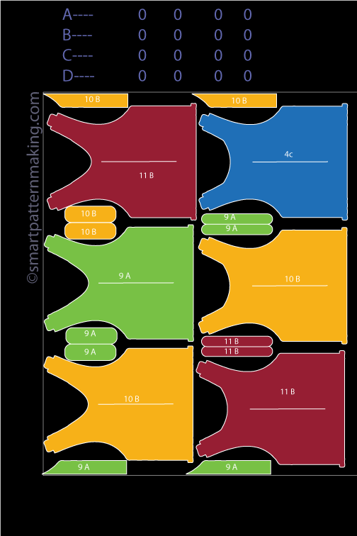
- Deliver a trimmed ZIP containing only required sizes and layers for production use.
Request file-size optimization in the conversion order via the CAD File Conversion Service.
21. How should files be packaged and named for multi-style transfers?
Package as structured ZIPs with a manifest: styleID_folder containing CAD files, PDF proof, graded spec sheet, and a layer-mapping README.
- Manifest fields: style, season, base size, revision, date, and responsible engineer.
- Consistent naming accelerates factory intake and reduces misfiled assets.
Use the provided manifest template when submitting a multi-style transfer or request it via the project intake.
22. How to deliver files securely to factories and protect IP?
Use secure download links (SFTP or encrypted cloud links), require NDA prior to transfer, and include a delivery manifest to log access and versions.
- Do not email raw CAD attachments; prefer authenticated file delivery with expiration and access logs.
- Our team can package and deliver files under NDA on request.
Request secure delivery and NDA handling during intake via the project intake.
23. How to request custom exports for specific cutter models?
Provide the cutter vendor, exact model, and their CAD spec sheet so the export can be tailored to that machine's import profile.
- Include HPGL/PLT settings, required DXF version, AAMA preferences, and any pen mapping or offset tolerances.
- Custom exports reduce import errors and cutting-room setup time.
Upload cutter specs with the order and request a tailored export via the CAD File Conversion Service.
24. How to verify converted files with measurement checks?
Overlay converted output on the source file, verify three to five key POM dimensions, and confirm seam-length parity and notch alignment.
- Automated scripts compare coordinates; follow with manual visual overlay and PDF sign-off.
- Document verification results in the delivery manifest for factory reference.
Include a verification pass in the conversion scope or request it via the CAD File Conversion Service.
25. Can CAD exports include grade rules or only separated sizes?
Exports can include both: retain grade-rule metadata in Gerber .ZIP, and deliver separated-size DXFs for production cutting as required.
- Gerber .ZIP preserves grade rules; separated DXFs are preferred for cutting rooms that cannot read grade metadata.
- Always deliver a graded spec sheet alongside separated-size outputs.
Specify desired outputs (Gerber .ZIP + separated DXF) when ordering via the Grading & Export Service.
26. How to handle archived versions and version control for CAD files?
Use revisioned filenames, a central archive with immutable ZIPs, and retain at least two prior revisions with changelog notes for traceability.
- Example: S123_Shirt_M‑01_rev02_2026‑04‑29.zip with changelog.txt documenting diffs.
- Store master copies offline and expose delivery copies via secure links.
Request archival packaging and version-control manifest via the project intake.
27. What checks prevent data loss during format conversion?
Run layer reconciliation, curve overlay, notch/drill verification, POM comparison, and produce a signed PDF proof to confirm integrity before release.
- Automated checks detect missing geometry; manual inspection confirms notch placement and seam parity.
- Sign-off by the engineering lead reduces factory iterations and rejects.
Include an engineering sign-off QA in the conversion order via the CAD File Conversion Service.
28. How to request support if a factory cannot open the file?
Provide the factory error screenshots, the CAD export version, and the target system specs so the file can be re-exported or repaired for compatibility.
- Common fixes: re-export to a different DXF version, run cleanup, or produce a PLT for plotter verification.
- Our team diagnoses quickly and issues a repaired file within the standard 24–48 hour window.
Submit factory error details through the CAD File Conversion Service for rapid troubleshooting and repair.